Welcome to BIOMED SIMULATION Knowledge Base
Instructions to Replace the Embedded Board Stack in CPM
BACKGROUND:
Follow these instructions to replace the existing embedded board stack in a Califia Patient Module with a new board stack.
- PREPARATION:
- Drain the reservoir in its entirety.
- Power off the unit
- Disconnect all external tubing.
- Disconnect the power cable and Ethernet cable.
- Move the Califia Patient Module to a table or benchtop with plenty of workspace.
- REQUIRED TOOLS:
- 2mm hex driver
- REQUIRED PARTS:
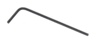
- New embedded board stack, Figure 1.

Figure 1. Embedded board stack
- PROCEDURE:
- Remove top panel, Figure 2, use 2mm hex driver to remove all screws (a total of 14 screws)
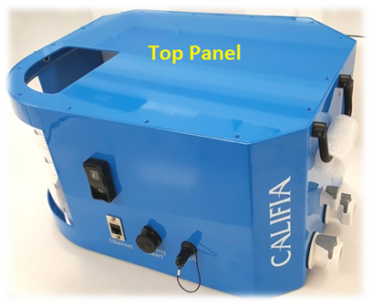
Figure 2. Califia Patient Module
Figure 3 is a top view of the Califia Patient Module with the top panel removed. The reservoir, ①, is labeled for orientation. Work will be carried out in ② Computer board.
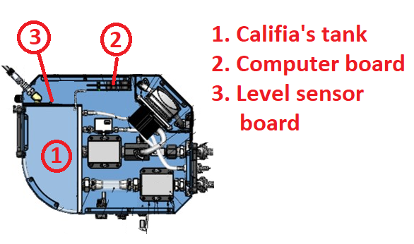
Figure 3. Work overview illustration
- Disconnect all connectors from existing board stack. Figure 4 shows a list of cable harnesses that need to be removed. To remove each of the connectors, grab firmly and wiggle sideways while pulling up.
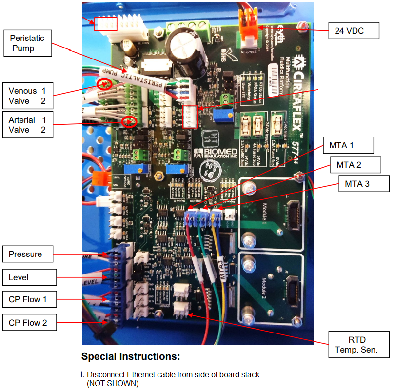
Figure 4. All connectors attached to top board
- Detach board stack from panel. Refer to Figure 5 to remove 6 screws. Hold the board stack and carefully remove from Califia Patient Module. Note there is one more connector to remove in the back of the board, Beating Heart (BMCA-0006), Figure 6.
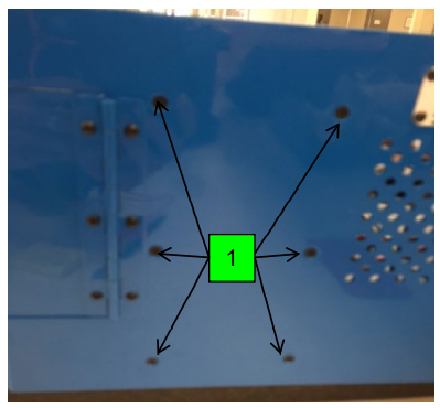
Figure 5. 6 screws securing board stack to rear panel
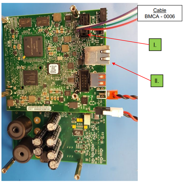
Figure 6. Beating heart connector in bottom board of stack
- Place new board stack in same location. Attach the Beating Heart cable to bottom board connector, as shown in Figure 6. Mount board stack to rear panel using the same 6 screws removed in previous step, refer to Figure 5.
- Board stack is ready to attach all connectors. Refer to Figure 4. Please double- or triple-check each of the connectors to ensure they’re in the correct terminals and proper alignment. Figure 7 offers a good angle to use for comparison.
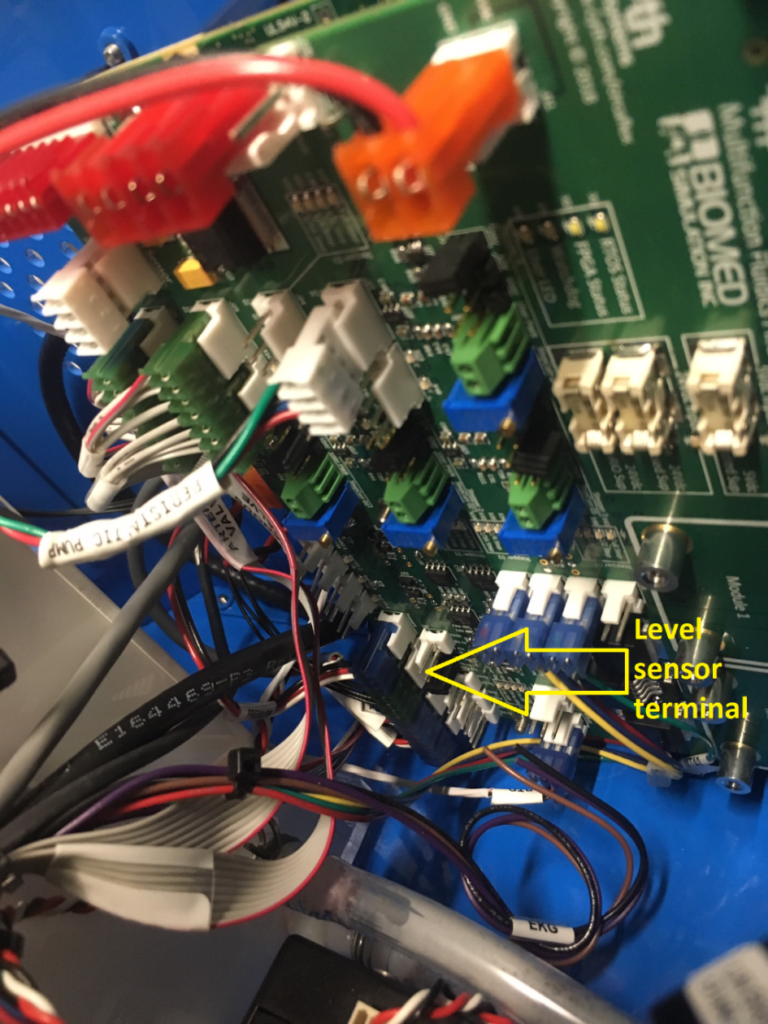
Figure 7. Mounted computer board – level sensor terminal labeled
- Next is to attach power and external ethernet cable then power up the Califia Patient module. Listen for the valve initialization routine that takes place approximately 20-25 seconds after power up. Once initialization is successful, launch Califia Simulator software and connect to the Califia Patient module, as usual.
- If there are any problems or concerns, please contact Biomed Simulation personnel for support.