Instructions to Replace and Configure the CALIFIA® Simulator System Level Sensor in the Field
BACKGROUND:
The level sensor used in a Califia Patient Module (Califia) reservoir measures fluid volume by sensing electrical capacitance inside the reservoir. The following instructions can be used when replacing the level sensor in a Califia Patient Module and configuring it via the Califia Simulator software.
- PREPARATION:
- Drain the reservoir in its entirety
- Power off the unit
- Disconnect all external tubing
- Disconnect power cable and Ethernet cable
- Move the Califia Patient Module to a table or benchtop with plenty of work space
- REQUIRED TOOLS:
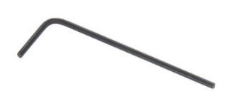
- 2mm hex driver
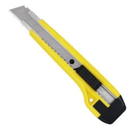
- Long blade
- REQUIRED PARTS:
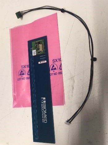
- Level sensor with wire harness
- PROCEDURE:
- Remove top panel, Figure 1, use a 2mm hex driver to remove all screws (a total of 14 screws)
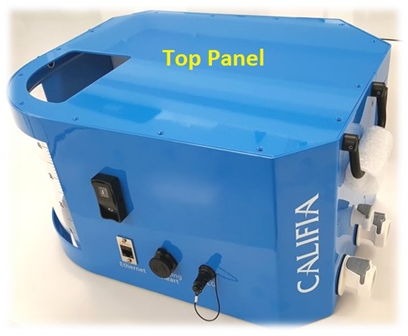
Figure 1. Califia Patient Module
Figure 2 is a top view of the Califia Patient Module with the top panel removed. The reservoir, ①, is labeled for orientation. The key components where work will be done are ② Computer board and ③ Level sensor board.
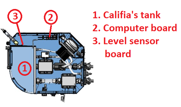
Figure 2. Work overview illustration
- Remove the digital level sensor
- Identify the level sensor taped to the side wall of the reservoir, indicated by ③ In Figure 2. The sensor is a circuit board running the height of the reservoir, see Figure 3.
- Disconnect the cable connector by firmly wiggling it out. Follow the level sensor cable to the computer board; it may go to one or two different terminals. Make sure to find the terminal(s) and disconnect cable from each.
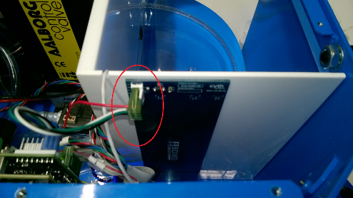
Figure 3. Digital Level sensor and connector circled in red
- Remove the level sensor board from the reservoir. Carefully wedge the metal blade in between the level sensor board and reservoir, Figure 4. grab the board from the top edge and pull away until it’s fully removed. Make sure to remove any residual tape from the reservoir wall.
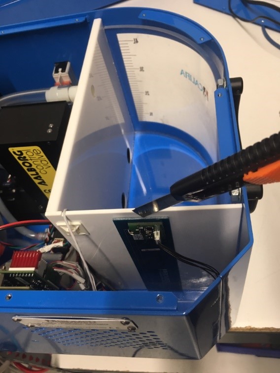
Figure 4. Remove the level sensor by wedging the blade between the level sensor and the reservoir
- Apply new level sensor
- Use blade to remove tape protection from back of level sensor, Figure 5.
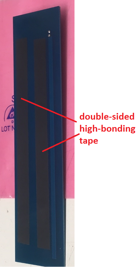
Figure 5. Back of level sensor with double-sided tape strips
- Carefully stick new level sensor to tank – same location as old one. Make sure it lands as straight as possible for best performance. Insert new level sensor cable connector (small white connector) into level sensor terminal.
- The other end of the new level sensor wire harness ends at a specific terminal in the computer board. For clarity, Fig. 6 shows a top view of the computer board before mounted and no cables obstructing the view. The label points to the location the level sensor cable terminates. Figure 7 is an actual example of the same board mounted with all cables in the way. Please try to identify this terminal and carefully secure the wire harness connector. To help with the connector orientation, notice the wires come out of the connector pointing away from the board.
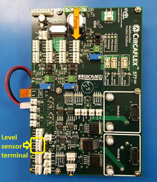
Figure 6. Computer board top view – level sensor terminal labeled
Figure 7. Mounted computer board level sensor terminal labeled
- Preparing Califia Patient Module for testing
- Mount the top panel but do not secure with screws yet
- Connect power cable and ethernet cable to Califia Patient Module
- Connect circuit tubing (Arterial, Venous, Cardioplegia and Vent)
- Power up the Califia Patient Module
- Launch the Califia Simulator software in your computer; it should recognize the Califia Patient Module
- Level sensor configuration
- In Opening Screen, select CPB and press the Continue button
- Press the Califia Controls button, ① in Figure 8
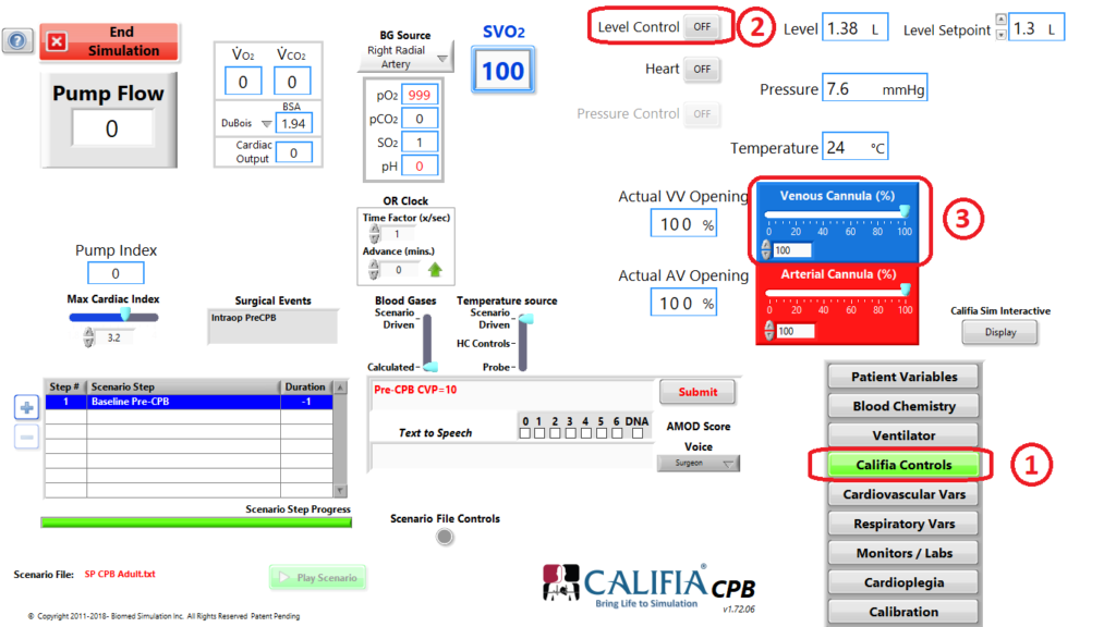
Figure 8. Califia Controls settings before level sensor teaching process
- Set the Level Control button to OFF, ② in Figure 8
- Set the Venous Valve slider to 100%, ③ in Figure 8
- Press the Calibration button, ① in Figure 9
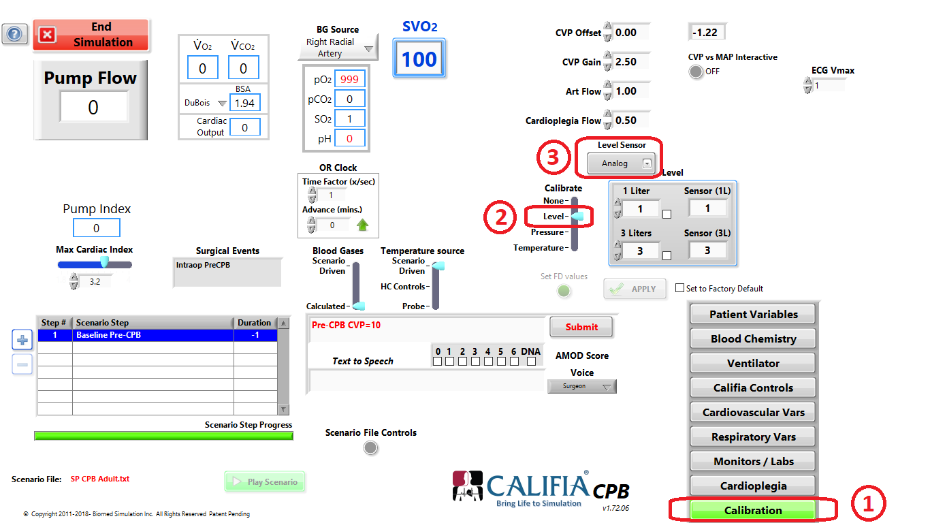
Figure 9. Calibration settings before level sensor teaching process
- Press the following keyboard combination: <Ctrl>-<Shft>-Q
- Set the Calibrate slider to Level, ② in Figure 9
- Select Analog from the Level Sensor selector, ③ in Figure 9
- Set Calibrate slider to None then back to Level
- Press F11 key in keyboard
- Clamp the venous return and use a pump to fill Califia’s reservoir to the 600 mL mark
- Once the volume is stable (not moving around), press the Low Level Teach button, ① in Figure 10. The process takes about 20 seconds to complete. You will hear a series of audible clicks coming from the Califia Patient Module computer board
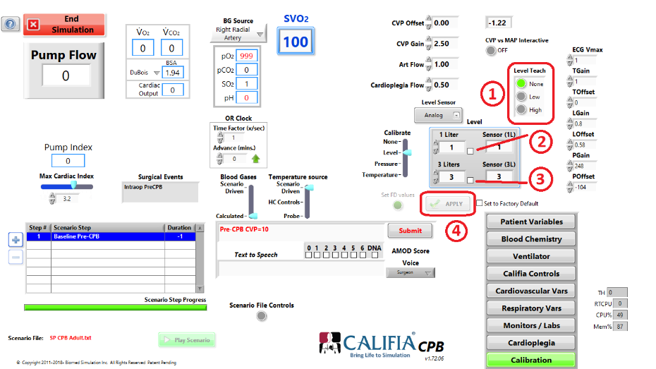
Figure 10. Level Teach buttons in Calibration section
- Fill Califia’s reservoir to the 3.6 L mark
- Once volume is stable (not moving around), press the High Level Teach button, ① in Figure 10. The process takes about 20 seconds to complete. A few audible click sounds are made.
- Empty Califia reservoir to the 1 L mark
- Once volume is stable; press the checkmark box next to 1 Liter, ② in Figure 10
- Fill Califia reservoir to the 3 L mark
- Once volume is stable, press the checkmark box next to 3 Liters, ③ in Figure 10, then press Apply button, ④ in Figure 10
- Go to the Califia Controls section, verify Level indicator reads 3 Liters; verify it reads properly at two other volume marks, say 2.5 L and 1.5 L.
- Return to Calibration section
- Set Calibrate to Level, ① in Figure 11, then place checkmark next to Set to Factory Default, ② in Figure 11, then press Set FD values, ③ in Figure 11
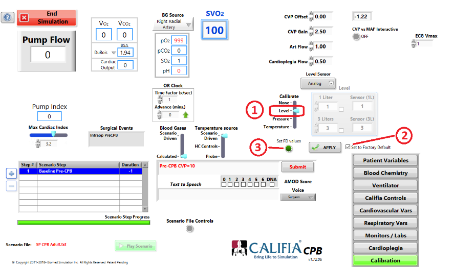
Figure 11. Set Level Calibration values as factory defaults
- Return to Califia Controls and set Level Control button to ON
- Test the Califia system by going on and off bypass to make sure the system responds as expected
- These are all the modifications. Prior to replacing the Califia top cover, perform a visual check to make sure all new connections are in place and tightened up